:workshops:2016_deliveries:lock:20161215_0106.jpg
Lock Making and Picking
This workshop was developed at The Edge by Phil Gullberg and this version is from the second delivery at Woodford. 2016.
Summary
During this workshop you will learn how to make and pick a lock.
While at Woodford, you can follow along and download a pdf of this Workshop by connecting to our wifi network: TheEdgeWorkshop and downloading from the admin menu at the top right.

Step Zero: The Pin Tumbler Lock and Your Kit
Basic principles of the pin tumbler lock may date as far back as 4000 BC in Egypt.
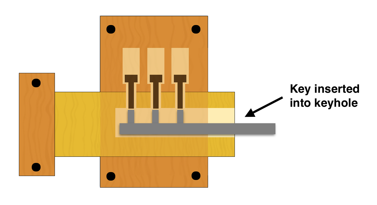

In 1848, Linus Yale, Sr. invented the modern pin-tumbler lock.
In 1861, Linus Yale, Jr. was inspired by the original designed by his father.
He invented and patented a smaller flat key with serrated edges as well as pins of varying lengths within the lock itself.
The same design of the pin-tumbler lock is in use today.
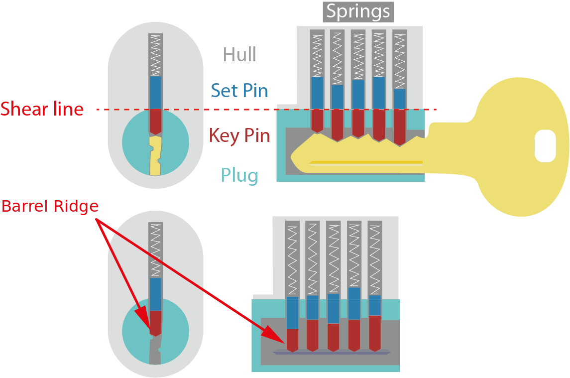
How a Modern Pin Tumbler lock Works
The set pins keep the lock shut. They rest on top of the key pins which are kept in place by the barrel ridge. The key lifts the set pins above the shear line, allowing the lock to turn.
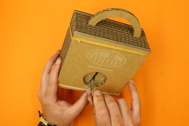
Your Lock
Your lock kit contains a pin tumbler lock set in a padlock. The padlock is held shut with magnets when locked.
The bulk of your kit is made from cardboard to keep costs as low as possible.
This means that we can't make a barrel ridge that will stand up to the test of picking. So we've modified the the mechanism, with Orings on the key pins to keep them in place when locked.
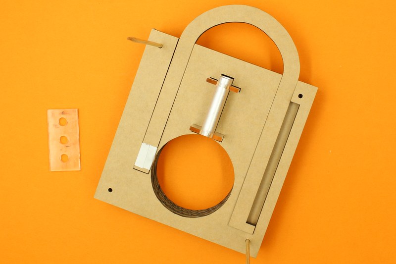
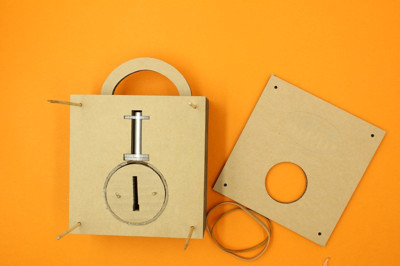
Kit Parts
Please check you have all your cardboard parts
And all your other parts
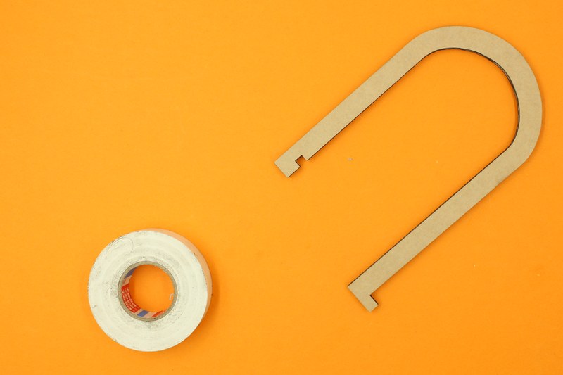
Shared Tools
Some simple tools required during the workshop, these are shared.
- Side cutters (for biting off skewers)
- electrical tape
- Scissors (for cutting tape)
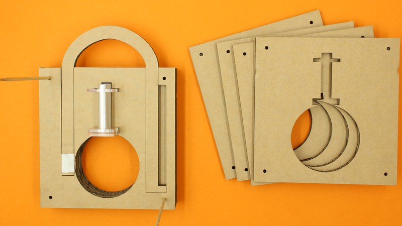
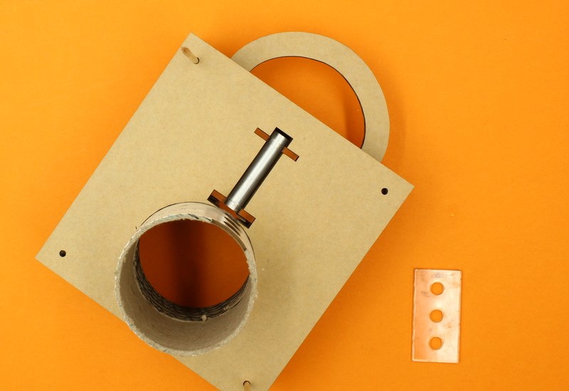
Step One: The Plug
We'll start by putting our plug together. Before we start, make sure that the skewer holes in your cardboard segments are punched out, and note each plate has a number on the bottom front side.
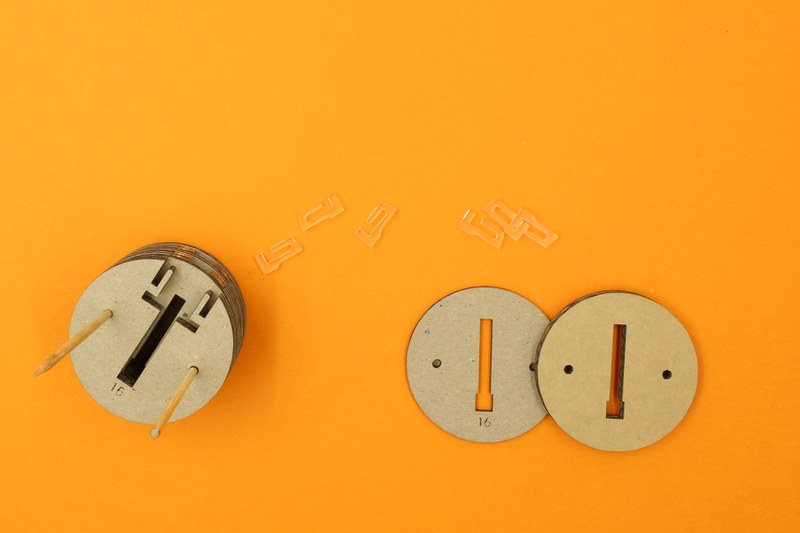
Assemble the first five plates of the plug
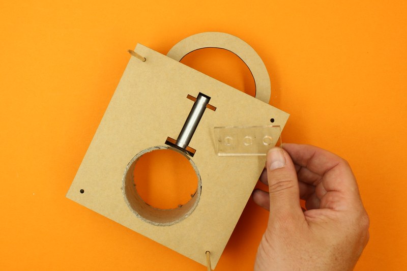
Add the plastic plug supports. Carefully use the pointy end of a skewer to nudge the plastic plug supports into place

Then add two cover plates to hold it all together - plug plates #6 & #7
Now we will add another three plates.
(Note the notch in the left hand side of plates #8 & #9.) This is where one of our magnets will go… but we'll come to that in a moment

And again we add the plastic plug supports to these three layers
And then two more cover plates
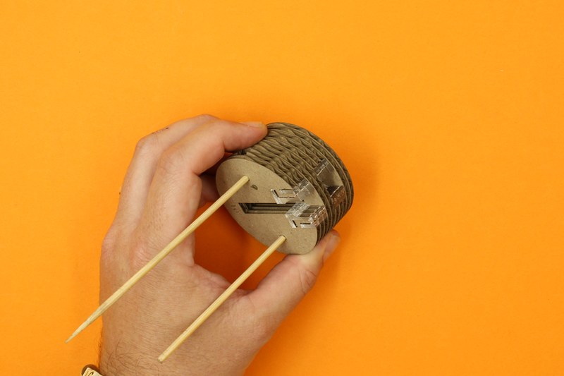
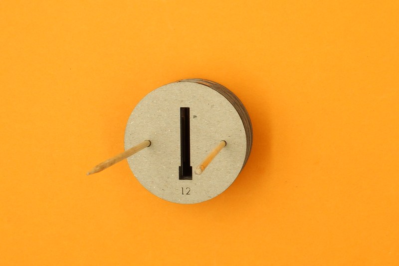
You should be up to plug plate #12

Now add the last three layers of plug plates and the two plastic plug supports for each layer
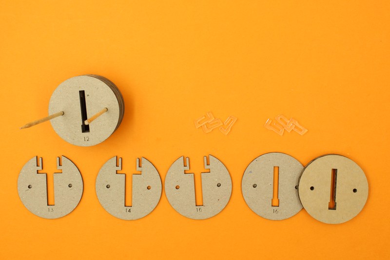
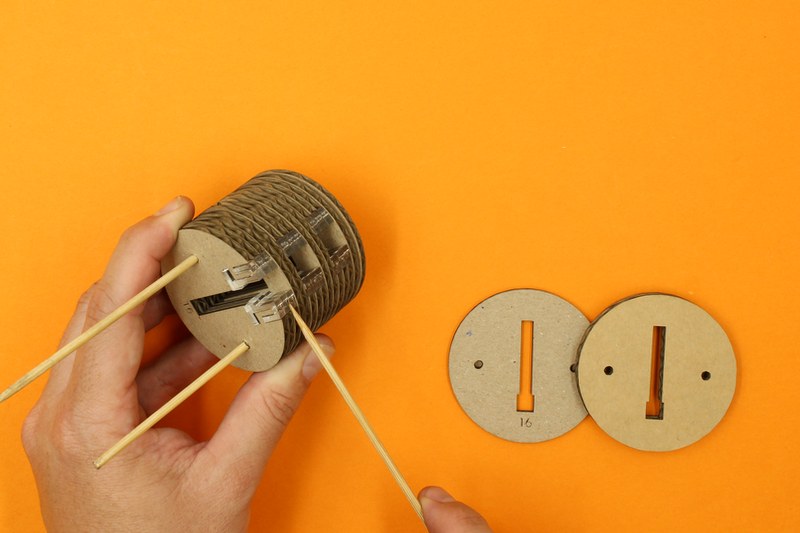
And now get plug plate #16 on top to hold it all in place. You don't want it to fall apart
Step Two: Tape in Plug Magnet
Now we are going to add the magnet and tape it all together
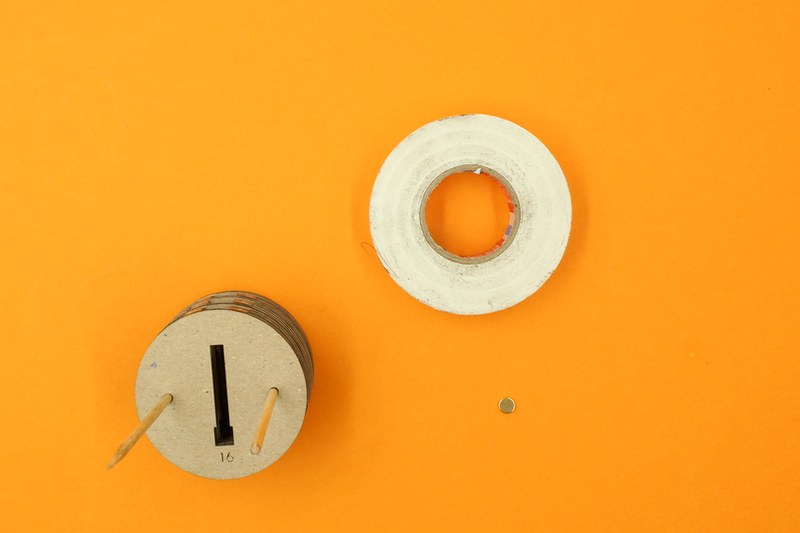
Can you see the magnet in its notch on the left hand side (if you are looking at it from the front)?
Carefully remove the skewer on the left hand side of the assembled plug …
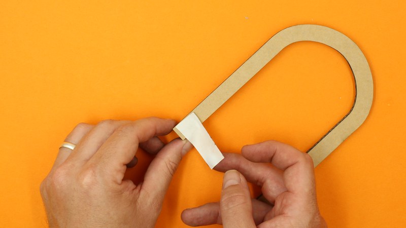
and starting here, tape around the “equator” of your plug…
Tape over the magnet…
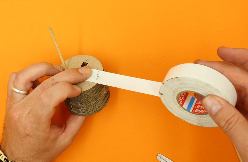
Around the back…
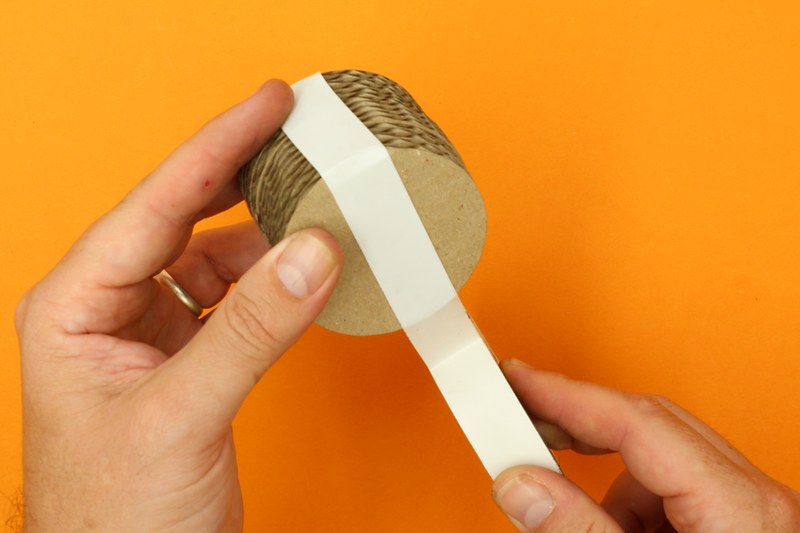
Carefully remove the second skewer without disturbing the alignment of the layers
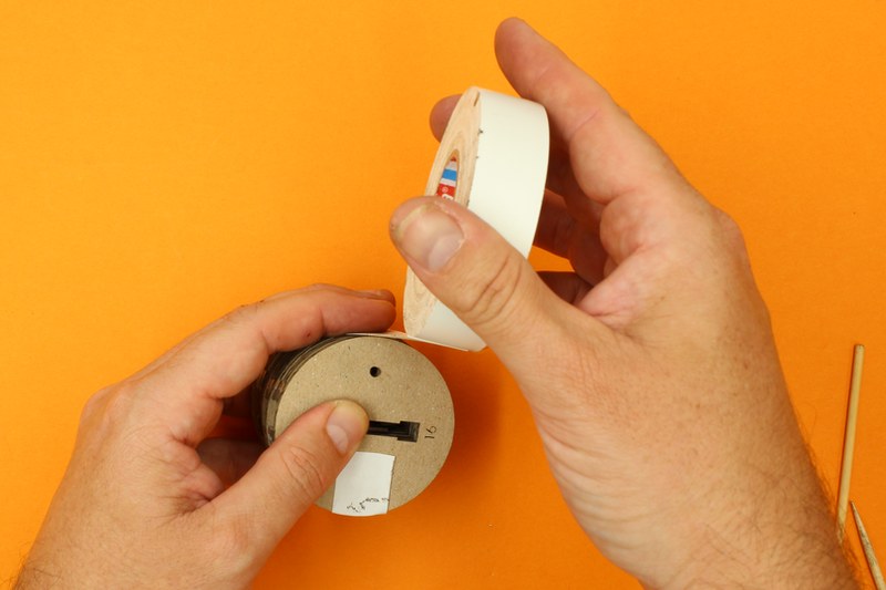
Trim the tape to the required length.
Make sure you are not compressing the cardboard too much but also that there isn't any space between the layers

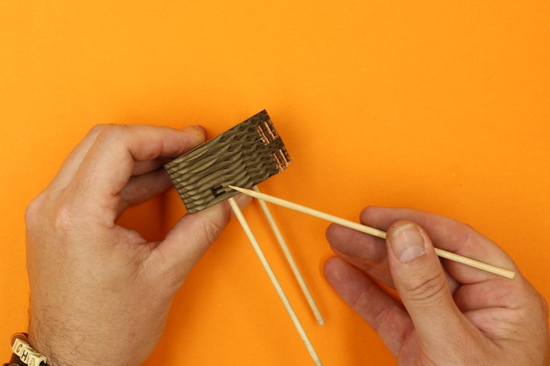
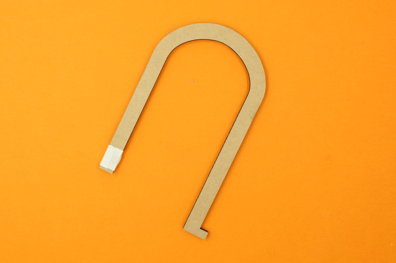
Now we are going to push the pointy ends of the skewers through the tape and back into their holes
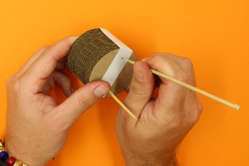
All the way through the plug and out through the tape on the front
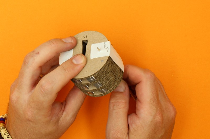
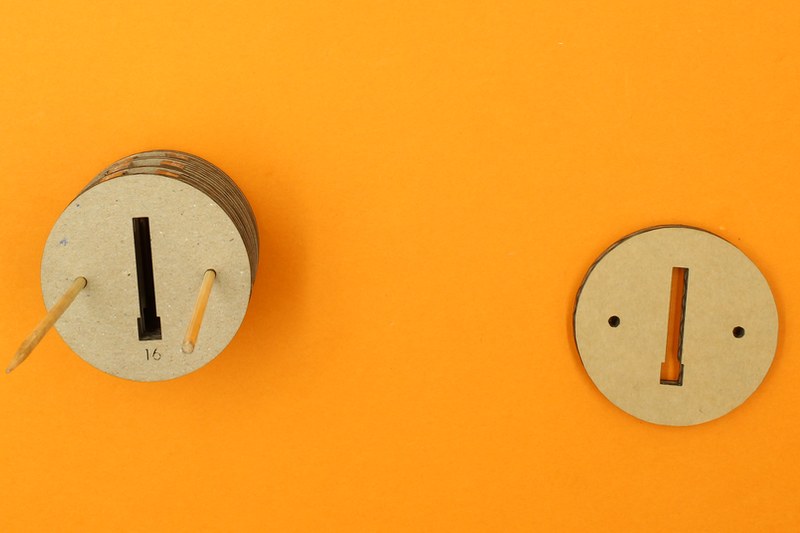
Make sure the two skewers are flush on the back of the plug…
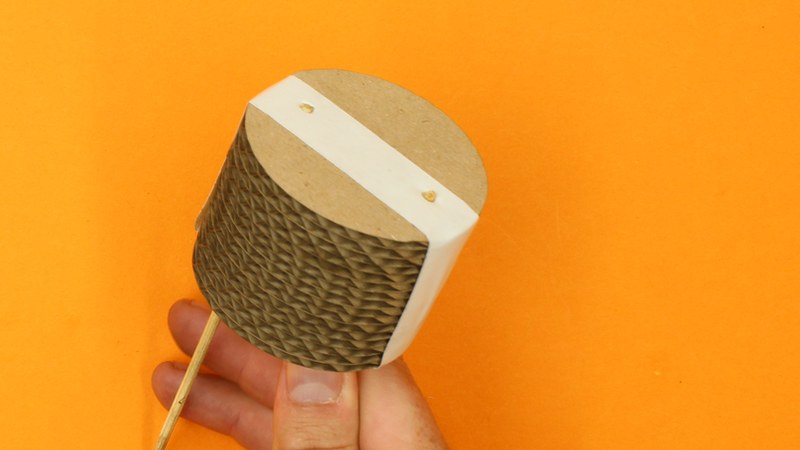
Now we are going to add the front cover for the plug
This front cover is 6mm, a bit thicker than the other layers, cut out of the double-ply corrugated cardboard that the hull parts are cut from
When you have this front cover in place, trim the skewers to the required length with the side cutters. Make sure you hold on to the bit you're cutting so it doesn't fly off and take out an eye!

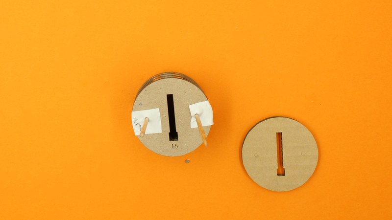
Step Three: Fit Plug Sleeve
Now we are going to get our plug sleeve ready and test that the plug will spin smoothly inside it

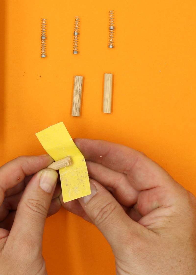
Take your little piece of sandpaper and smooth off the rough edges on the plug sleeve
When you've done this insert the plug and check it turns smoothly in the sleeve

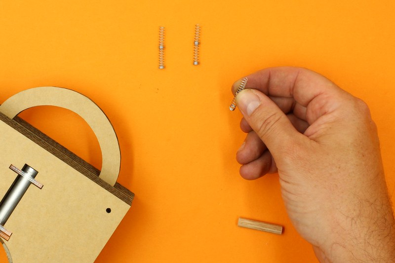
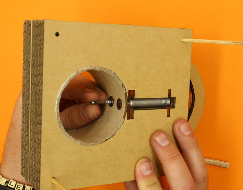
Step Four: Install Key Pins
Now we are going to install our key pins and test their function
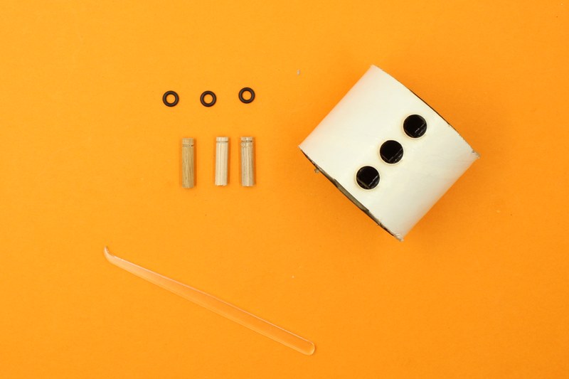
The key pins are the three shorter dowels (24mm long) with a groove cut into them. Seat the Orings on to the three key pins

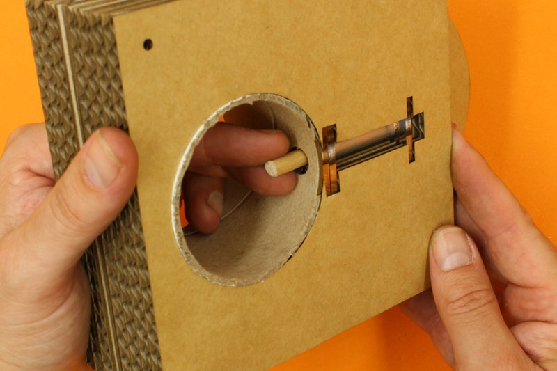
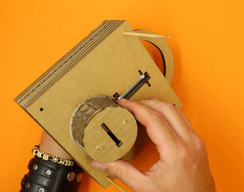
Insert the pins into each of the chambers…
and check their function (i.e. that they move up and down freely) by manipulating them using you pick via the key hole
If you have got this far...Congratulations!
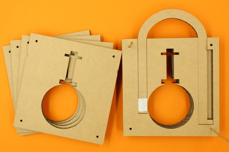
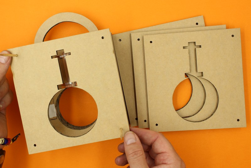
Step Five: The Hull

The hull consists of 10 layers:
- 1x front smaller hole (has etching on it)
- 1x back no hole (has The Edge logo on the back)
- 1x hasp layer
- 7x filler layers
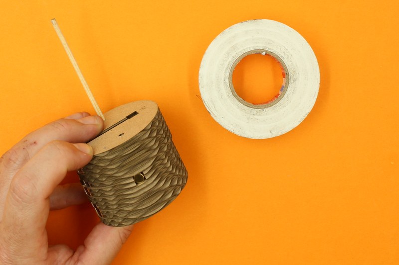
First of all take your hasp layer and carefully remove it. We are attaching the other magnet to the hasp
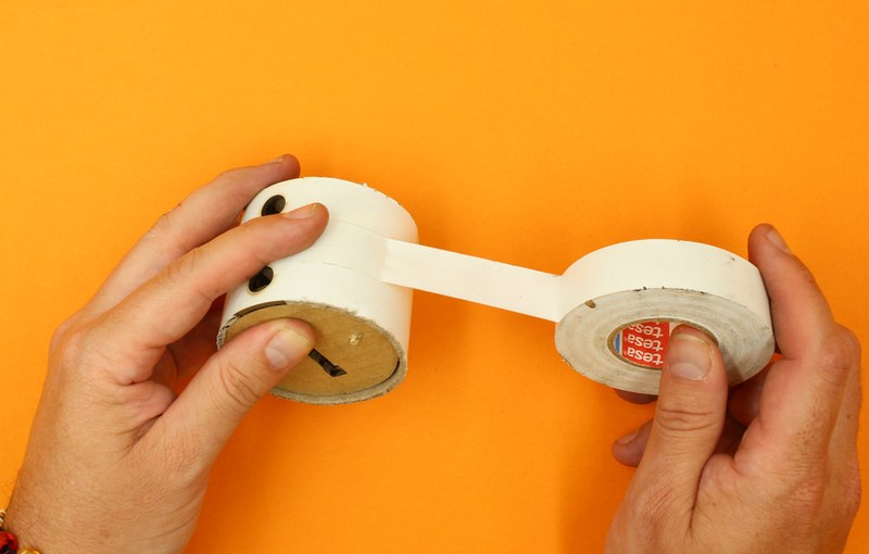
Make sure the polarity matches the polarity of the magnets in the plug.
An easy way to do this is to put your plug in the white tube (to make the removal of magnets easier) and let the magnets snap together on the outside. This way you'll know which side should point in or out.
Make sure the magnet in the hasp doesn't stick out too much and add a piece of tape to keep it in place

Don't use too much tape as it will add unwanted friction
Put the hasp back into its layer before the next step
Now we start putting our Hull together
Just as we did with the Plug, start by aligning three of the Hull “Filler” plates on two of your skewers. Then add the Hasp layer of your lock.
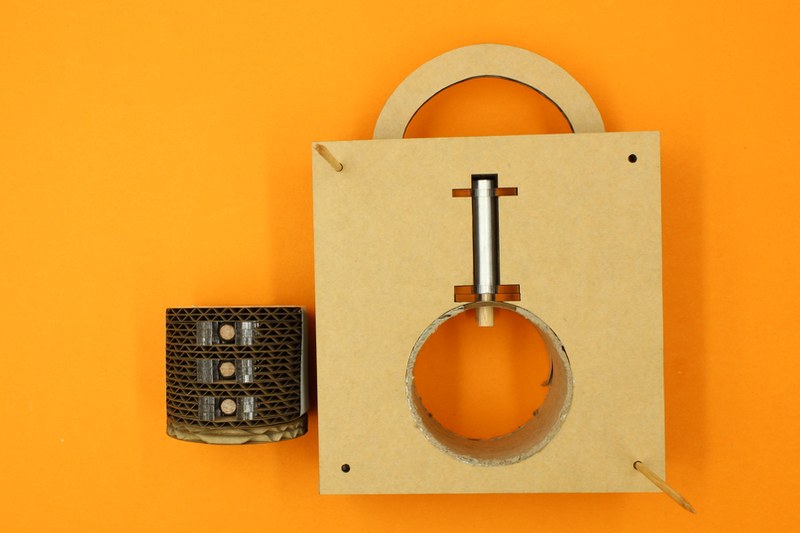
Step Six : Construct Top Pin Chamber Assembly
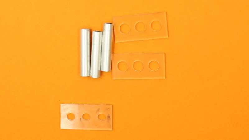
The following parts make up the Top Pin Chamber Assembly:
- 3x metal tubes (45mm long)
- 2x plastic supports with regular size holes (same diameter as the tubes)
- 1x plastic support with smaller holes
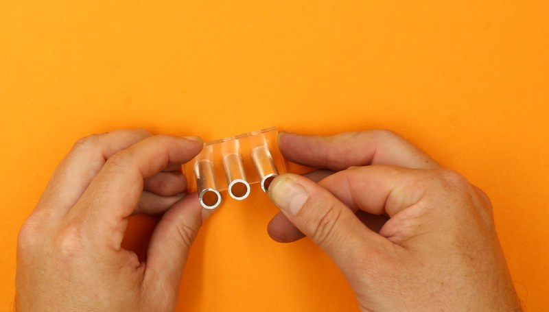
Start by fitting the middle metal tube into the centre hole of one of the plastic supports

Now add the second plastic support

Align the outside holes of the plastic chambers supports and fit the other two metal chambers

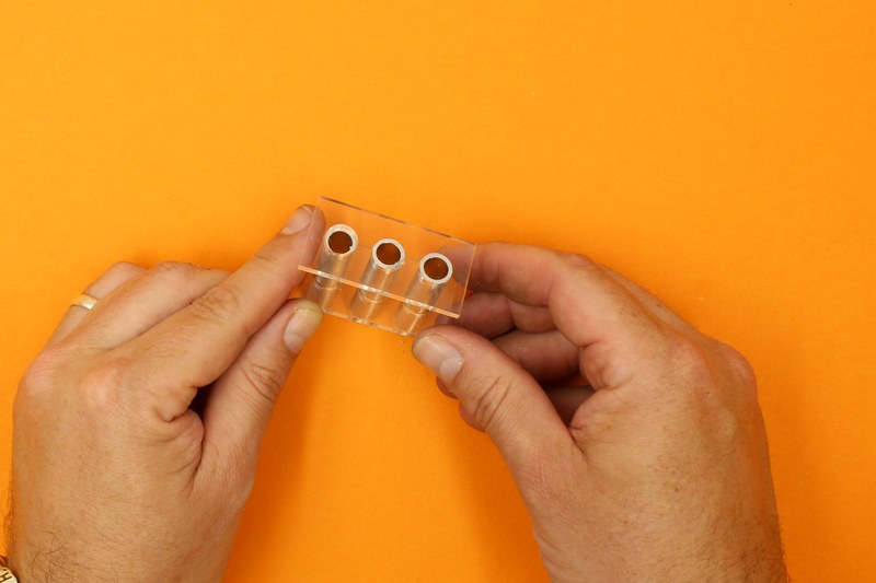
Now shimmy the top plastic support up the metal chambers until it is about 5mm from the top of the chamber
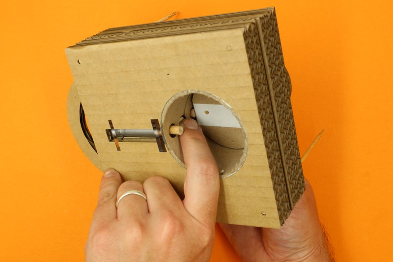
We'll now install the Top Pin Chamber Assembly into our half built Hull…
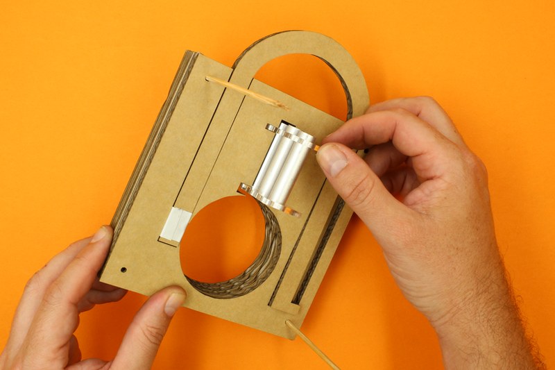
And slide the third of our plastic Chamber Supports (the one with the smaller holes) into the gap between the lower chamber support and the floor of the Chamber Assembly hole in the Hull Plates
This may require more patient shimmying

Step Seven: Complete Hull Assembly
We are now ready to complete the assembly of our Hull
Just add the remaining Hull Filler plates

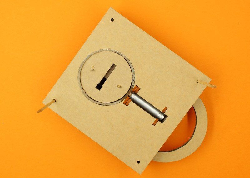
Step Eight: Fit the Plug into the Hull
We use tape to ensure the sleeve fits snugly inside the hull and won't rotate when we operate the lock.
First, add a strip of tape around the circumference of the Sleeve (postal tube).
Start the tape next to the middle hole, wrap it around the sleeve and trim the tape near the other side of the hole
Now remove the bottom plastic chamber support (the one with the smaller holes) and line the hole in the Plug Sleeve (postal tube) with the Chambers. When you have this accurately aligned fit the sleeve by pushing down into the Hull
Now replace the bottom plastic Chamber Support
Step Nine: Install Set Pins
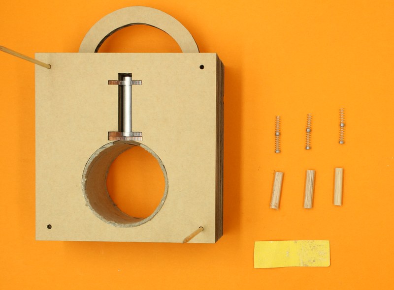
First deburr the set pins using the piece of sandpaper to ensure that they move freely in their chambers
Now install the springs. Make sure you have the springs up the right way
You want the smooth end at the bottom of the chamber and the rough end at the top of the chamber.
Hold your lock upside down the so the springs and pins don't fall out
Now install the pins into their chambers


Step Ten: Install the Plug in the Hull to complete the Lock Mechanism
Start by checking that your Key Pins are all sitting neatly in their Plug Supports…
and that none of the Set Pins or their springs have fallen out. (This will require patience!)

Orient the Plug so that the Key Pins and the Plug Support are at 90 degrees from the Chambers (i.e. 9 O'clock Position). The Chambers should actually be lined up with your tape
In one hand hold The Hull and Plug in position…

press the Set Pins one at a time so you can slide the plug into position
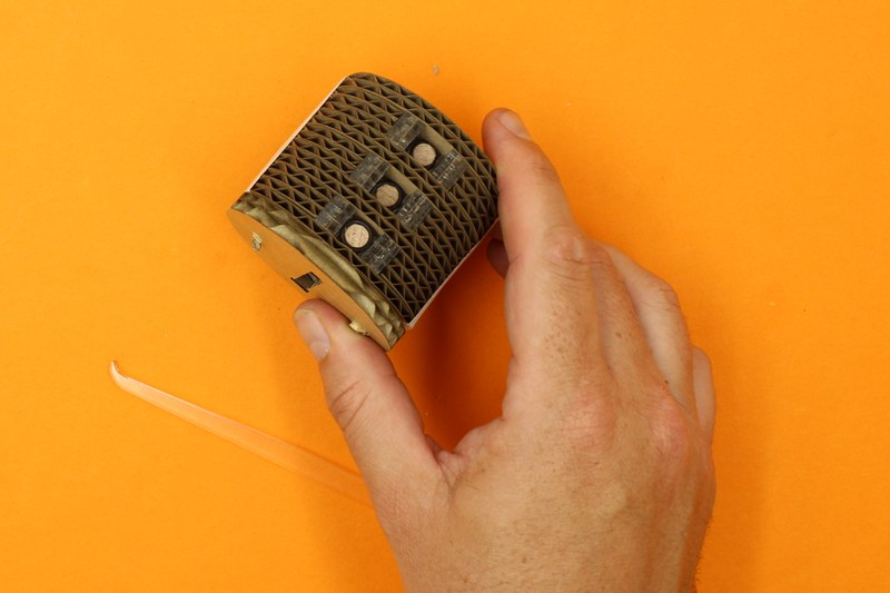
The back should look like this..
And the front like this
Step Eleven: Finishing Touches
Next we'll give our lock its finishing touches…

by adding the attractive “Limited Edition” back…

And Front Plates…
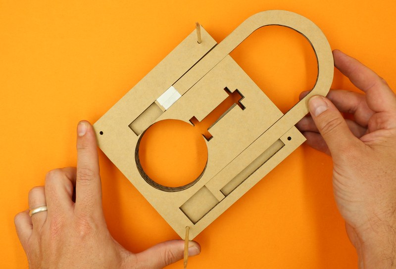
Add some rubber bands to keep it all together…
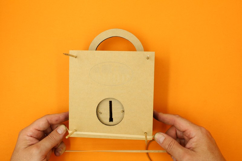
Add the last two skewers into their registration holes.
Finally, trim your skewers…
Congratulations!
You just made a cardboard Tumbler Lock!
The only thing now is to test if it actually locks.
And to pick it!
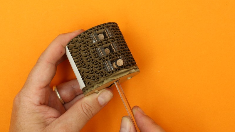
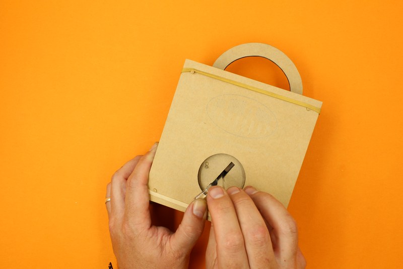
Step Twelve: Test and Pick Your Lock
To test your lock insert the long end of your tension bare (plastic “L” shape) into the square hole at the bottom of your key hole and rotate the plug until it is in the vertical home (12 O'clock) position
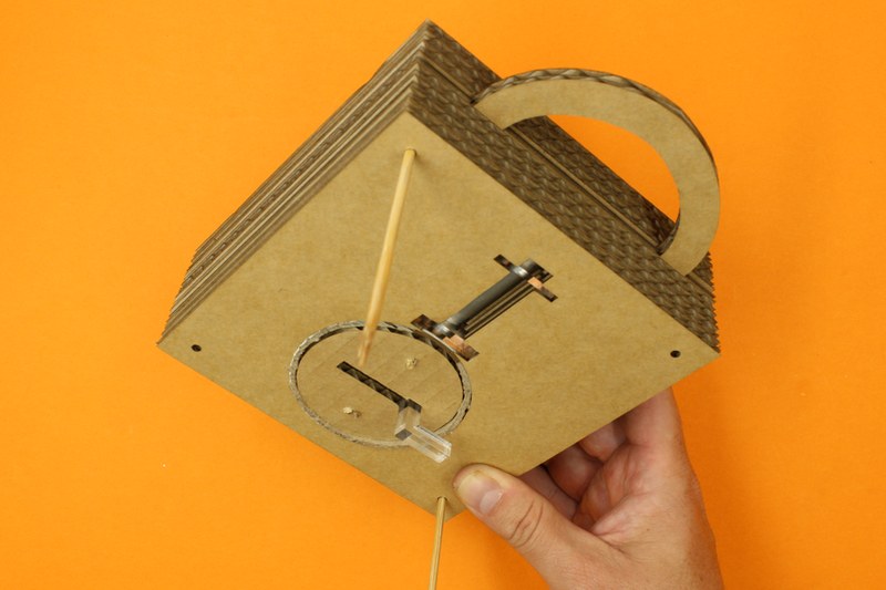
As you do this you should hear you lock click as the springs force the pins into position

Once it is in the 12 O'clock position and the pins are engaged, you should not be able to rotate the plug
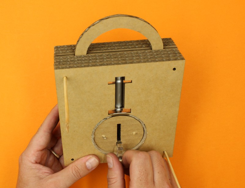
To pick the lock insert your tension wrench and use it to apply a slight rotational force (torque) to the plug
Then use your pick, via the keyhole, to momentarily raise the each of the Key Pins
If you are doing this correctly the torque on the plug should provide a small ledge for the set pin to rest on at the “Shear Line”.
Keep “picking” until you have all Set Pins resting on the ledge… when you do, the Plug will turn.
Good Luck!
And Remember

Production Notes
If you want to see how this workshop was put together, log in and check out the production notes