Vectric VCarve
This page is all about up-skilling you in VCarve to make best use of the CNC Routers. You will learn:
- An overview of CNC Routing and pre-production
- How to set-up and use your Vcarve Makerspace Client edition
- Standard Vcarve settings used in the Fabrication Lab including The Edge CNC tool database
- Basic vector optimising techniques
- How to troubleshoot vector issues
- Toolpath basics, tips and tricks
The Edge Fabrication Lab has a VCarve Pro Makerspace license.
This allows unlimited users to download a trial version of the VCarve Pro Software which is completely functioning except for the final stage of exporting of an Numerical Code (NC) file for a CNC router to cut, or other vector formats.
The License key for this offer is 86B4F-F467A-280D9-9F4C6-9C56B-4C528-BEE6F - you need to enter this in your version of Vcarve Pro.
You can design, layout and program tool-paths on your own machine at home save the file as a VCarve File, bring your file on a USB to your CNC booking.
The advantage to this is also that The FL supervisor has an opportunity to check the setting of a job before allowing it to be cut on our machine.
Again - The cut files can only be cut on The Edge's Makerspace licensed machines.
CNC Router Basics
A basic CNC Router is a simple machine, with a rotary tool (bit) moving along a path controlled numerically by a computer - ie. Computer Numerical Control (CNC). The diameter and cutting depth of the tool are key considerations when designing for routers.
To cut files on a CNC Router, we need to describe a path for our router move on. The most efficient way to do this is to use vector graphics. 2D points can be joined to create lines, curves, form polygons and other shapes to describe our path, which can then be converted to Numerical Code (NC), simple co-ordinates our machine understands 1).
VCarve Workflow Pre-Production
The basic steps are:
- Create a vector file
- Optimise/export your vector file
- Import into Vcarve
- Check/clean vectors
- Layout Shapes
- Create Toolpaths
- export to NC file
Creating a vector file is out of scope for this introduction - use these example files if needed or you can create your own iconic fretwork.
Optimizing your Vector file
There is the long list of things you can do to when designing and prepping your vector file to ensure that it is imported into Vcarve efficiently. While you can fix issues in Vcarve, its usually easier to do so in the original format.
Ensure the following before export:
- All you shapes are closed/joined paths
- Any text is converted to curves and closed/joined paths
- Any parts with multiple paths are grouped together so they can be moved around without disturbing their arrangement.
- There is not multiple copies of paths hiding behind your shapes/ parts.
- Your units are millimeters.
- Your design fits inside you material sheet size
- Your design is scaled properly
- Export your design in an appropriate format. We recommend using at least two formats:
- DXF (export as latest version available and R17)
- PDF
Using VCarve Makerspace Client Edition
It is imported to use The Edge makerspace ID - otherwise your designs will not open on the Fabrication Lab machines! To do this open the about menu

And enter The Edge Makerspace ID.
86B4F-F467A-280D9-9F4C6-9C56B-4C528-BEE6F
You will then have to close and relaunch VCarve.
Create a new Vcarve File
1. Click the new file icon or select the New option from the File menu

2. Choose Either a Single Sided Job or Double Sided Job in the Job Type (double sided jobs are ones that you need to turn the material over to make cuts on the other side)

3.The standard Job Sizes are 1200 Width(X) 1200 Height(Y) Thick 15 (Z).Ensuring you are using the mm option as your unit of measure.

4. Set the Zero Position for your job to Machine Bed!!!!!!!!!!!!!!!!!!.

5. Leave the XY Datum Position as the Default. Home is in the bottom left hand corner.

6. When you are happy with all these settings click Ok.

VCarve will then display a 2D workplane, with our vector tools off to the left.

You can always double check these settings in the Edit menu under Job Size and Position

Importing Vectors
Import your vector File by selecting the Import Vector icon in the File Operations Toolbar or select Import Vectors from the File Menu. If you don't have a vector handy - try this fretwork DXF.

Vcarve will import your vector to the bottom left corner of the Design Window ( zoom out if you can't see it )

Check/Clean Vectors
Now ensure that all the paths that make up the shapes of your job are closed/ joined. Select the Join icon from the Edit Tools Toolbar and select all the paths you want in a shape.

You may need to adjust the tolerance of the Join tool to ensure Vcarve can fill in the gaps between the multiple paths.

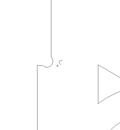
Next lets check our curves, this is important to ensure smooth cutting. Switch to Node Edit Mode

Then select one of your vectors. You will see either a nice smooth geometric lines (a line, arc or bezier)

Or an ugly collection of polylines

Zoom in and you will see the small line segements - these are to be avoided with CNC Routing

To fix this we will use the Curve Fit tool.

The aim here is to reduce the number of points, while still keeping the shapes you want. I've gone with circular arcs, and a tolerance of .5 mm

This turns this:

Into this

Not this (too large tolerance)

Tool fit and Assembly
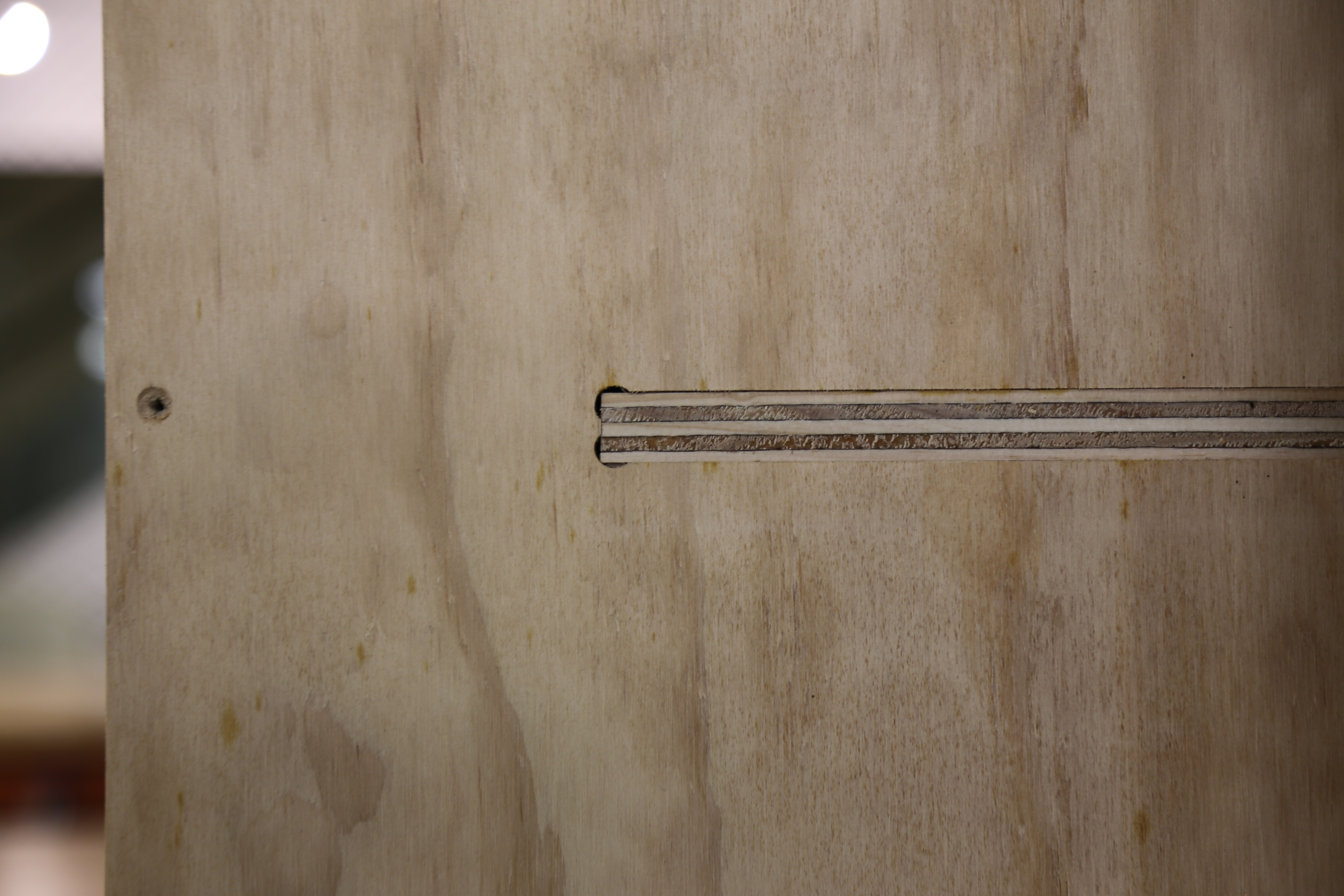
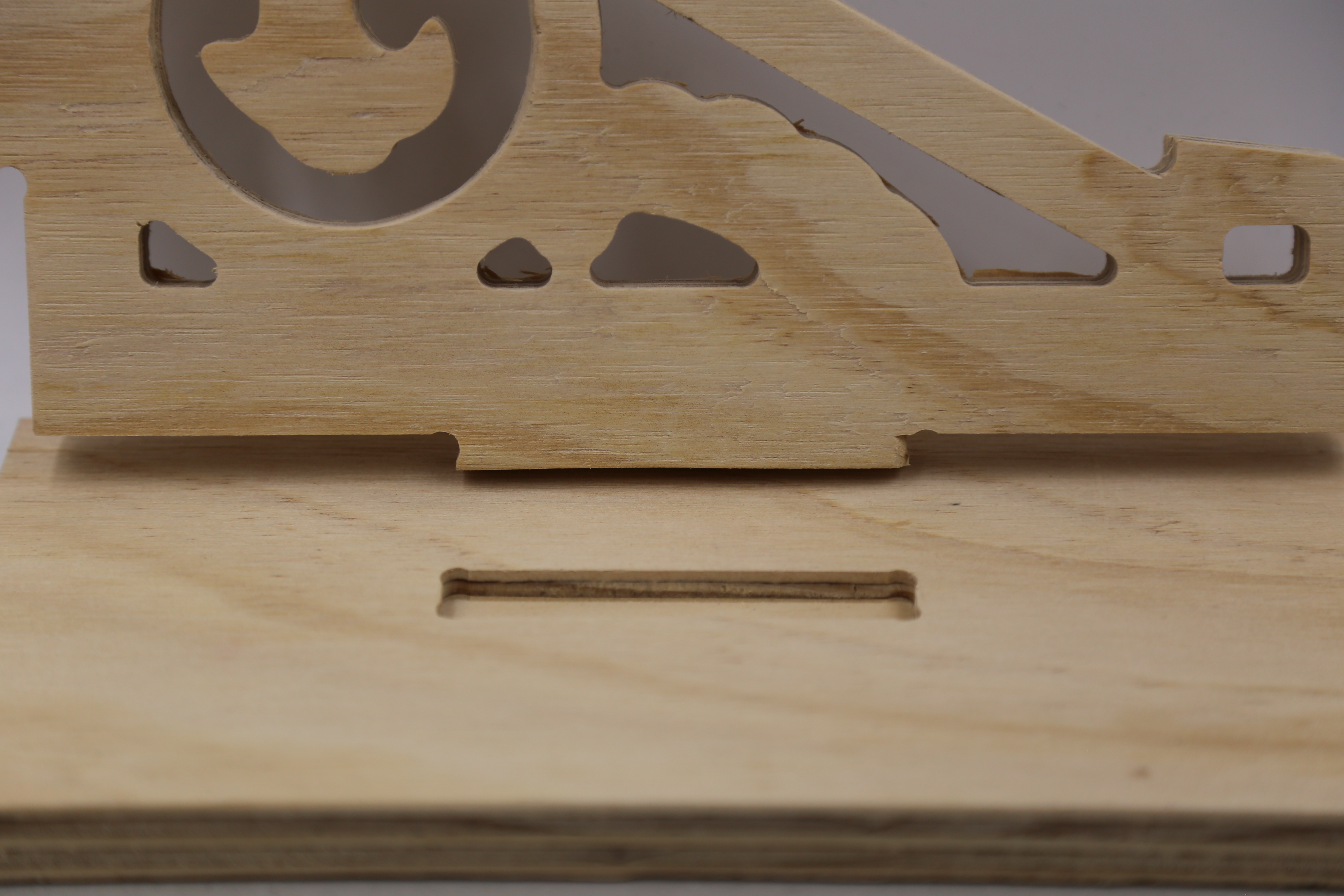
For this example job we are using an 6.25mm tool, so lets take a moment to measure our designs tight sections to make sure the tool will fit. otherwise we may produce a piece that looks like this.

Instead of:

This process will likely be repeated when we make toolpaths later on.
We will use the measuring tool.

Clicking on one edge, then the next, this section of the Fretwork is about 4.5mm wide. Too narrow for our (6.25mm) tool.

Node Editing
Lets widen that gap using our node edit mode. Click on our curve to select it.

Then drag and grab the points you want (they will go red) , then move them with the mouse - our nudge with the arrow keys.
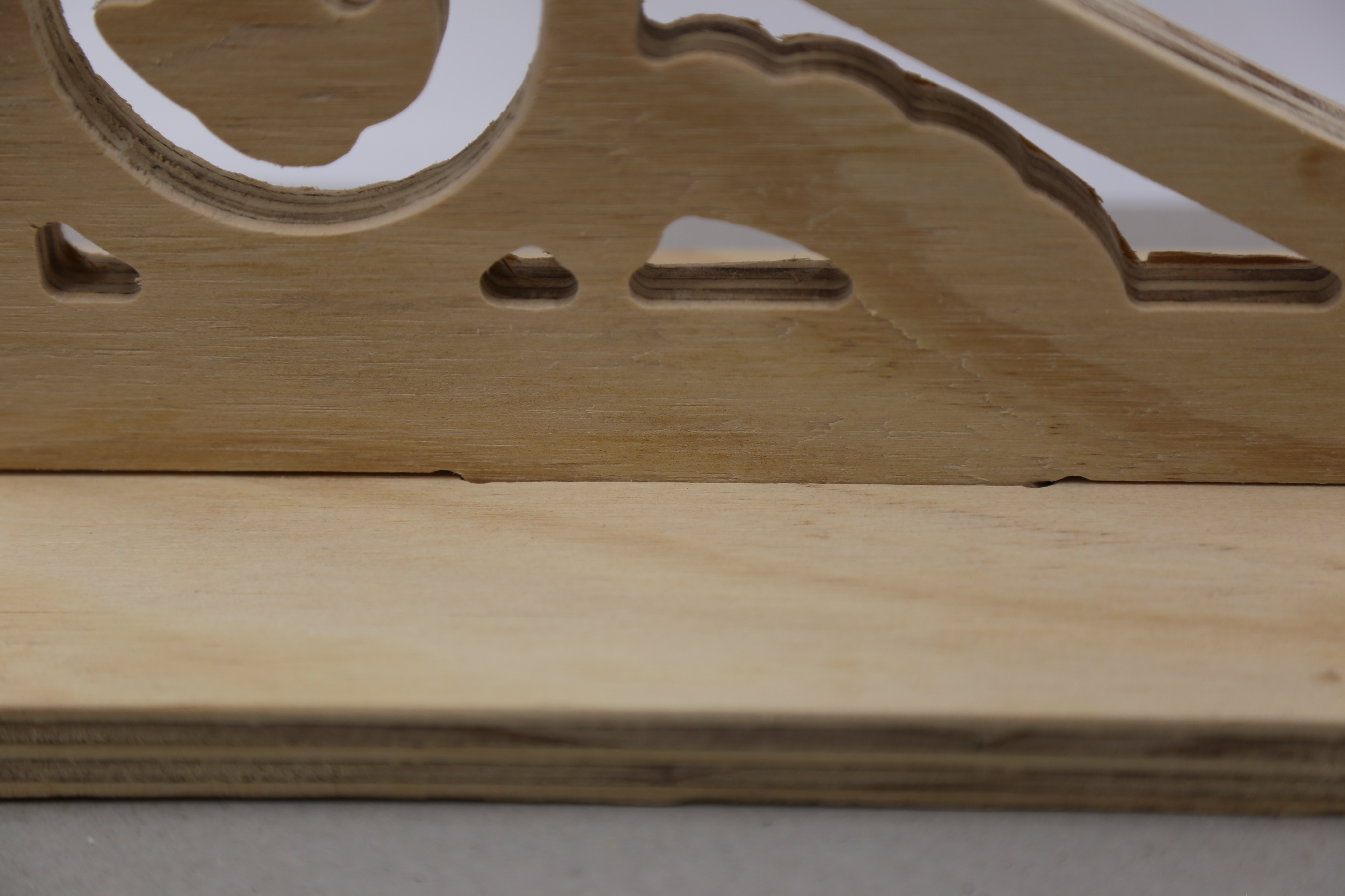
Dogbones
In order for our design to fit together straight of the machine - you may need to use dogbone fillets. This is a small arc on inside corners that fits the tool, and ensure a joint fits to its full length.
For our fretwork example to fit into a base, both the fretwork and base will need to be filleted.
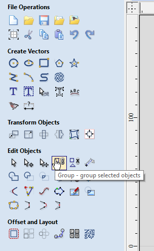
Use the fillet tool from the Edit Objects menu

And set the fillet/tool radius to 1/2 your tool diameter, selecting dogbone as the fillet type.
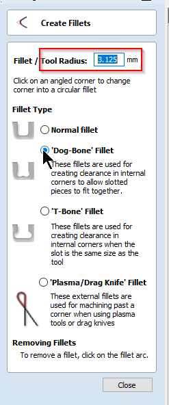
Then hover over an internal corner (you may have to ungroup your shapes first) until the cursor turns into a tick.

Click to produce a dogbone. If you can't add one - you may need to join your shapes.
Layout
Its time to move and arrange our design on the material - the first step is to group all the shapes so we don't lose our design. Use ctrl-a or drag and select everything, the use Ctrl-g to group (or the group menu button).
Group and Move
In the 2D View tab, select the Transform Mode selection tool form the Edit Objects Toolbar and drag the shapes into place on the rendering of your material. Or slow click on your shapes.
3. Once you are happy with the placement of the individual parts on the material, ensure that you do not have hidden / multiple copies of the paths that make up the shapes. Search for these extraneous paths by dragging or deleting ungrouped paths and undoing the operation when you have established you only have the paths required.
Setting up Toolpaths
Toolpaths are the path or route the CNC Router will move the spindle on. The path always follows a vector from your file.
The CNC Router requires more information about the type of tool you are using and how you want to cut/remove material. this is defined in the toolpath menus - found in the top right.

The Edge Vcarve Tool Database
Please use the latest version of The Edge Vcarve tool library. Download, unzip, then merge this into your version of Vcarve

1. Select a shape you want to apply a toolpath to.
2. Pin open the Toolpath Toolbars
3. Check the values in the Material Settings
4. Select one of the 12 types of Tool Operation you would like to apply to the toolpath - in this case
Remember to select the Tool operation order to optimize cut accuracy and minimize the effects of vacuum bed dropoff as parts toolpaths remove material. As a general rule use the following order:
- Drill and engraves and surface level pockets first
- Then cut through pockets, internal cut paths and large parts
- cut external paths small parts last.
Offset and Layout your cutting job
Once you are satisfied that all the required Paths are closed shapes you can layout the multiples parts required to be cut (Eg a 4 legs per stool and 6 stools are to be cut)
Using Vcarve @ The Edge
Vcarve Pro Makerspace edition is installed on the CNC Router PC in the Fabrication Lab and the laptop attached to the Xcarve. These instructions are based on cutting a standard job, one-sided with the stocked 15mm ply.